Model units & connections
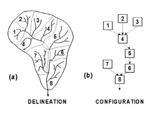
This page describes how modelling tools allow users to discretise catchments into modelled units in order to represent and calculate hydrological processes. Differentiating the catchment into separate components or units - such as subcatchments, patches of similar land cover, or soil layers with distinct properties - allows hydrological processes to be modelled by algorithms that have been developed for that scale and type of unit.
Each modelling tool has a unique way of describing a catchment in terms of:
- The types surface and subsurface model units that can be included
- The connections that can be defined between these different units
- The process algorithms that are used to calculate inflows, storage, and outflows for each unit
To set up a model of a specific catchment that is relevant to our understanding of it's processes (conceptual model) entails attention to modelling units and how they are, or are not, connected to one another. A flow path that we think is important in the catchment, and/or is important for the particular modelling project, may not be directly represented by certain modelling tools. For example, not all tools can include channel transmission loss in rivers, and those that do include it differ in where the water goes after leaving the model channel. When an important path or process can not be explicitly included using a given modelling tool, one may be able to represent it implicitly with parameter adjustment, or use another work-around, or chose to use another modelling tool.
Understanding how different modelled units work with one another informs how one may decide to discretise the catchment. Strategies may need to differ when using different tools. For example, models built in SWAT2012 and SPATSIM can both include irrigation fed from storage dams; however the two tools have different limitations in terms of where these dams sit in the model's subcatchments and in relation to the irrigated area. In SWAT2012, 'reservoirs' can be used for irrigation sources and are located specifically on the main channel at the outlet of a subcatchment. A reservoir can irrigate an area outside of it's subcatchment. In contrast, SPATSIM-Pitman only allows irrigation from 'dams', which are located internally in a subcatchment, not on the main channel, and so are only fed by a proportion of the runoff of the incremental subcatchment. These dams can only irrigate areas within the same subcatchment. These approaches would lead to different subcatchment delineation decisions when using the different tools.
This page summarises the unit types and connection options (i.e. flow paths) available across the tools. Their process algorithms are described on a processes page here. Although covered on separate pages, the approach to spatial unit and vertical layer discretisation and the process algorithms used are inextricably linked. This page summarises some implications of the structural differences across the tools, which are dealt with in more detail for some specific model application contexts in the specific use cases section, here.
The material on this page may be more depth than you are looking for. If all you need at the moment is an overview of the structures and capabilities of the different modelling tools, that summary can be found on the capabilities overview page, here
Basic approaches for representing catchments in the different modelling tools
The schematic diagrams and tables below describe the main discretisation approaches used in each tool in terms of breaking up catchments into units and specifying linkages. For MIKE-SHE, because the tool offers many options, two generalised set-up approaches have been described (more background on these is given here).
NB: For MIKE-SHE many structural options are available. Two generalised set-up approaches are used in these comparisons to represent the spectrum. These two are described here.
| Level / Element | WRSM-Pitman
(Sami GW) |
SPATSIM-Pitman
(Hughes GW) |
ACRU4 | SWAT2012 | MIKE-SHE, | MIKE-SHE, |
|---|---|---|---|---|---|---|
| Catchments
& subcatchments (subcats) |
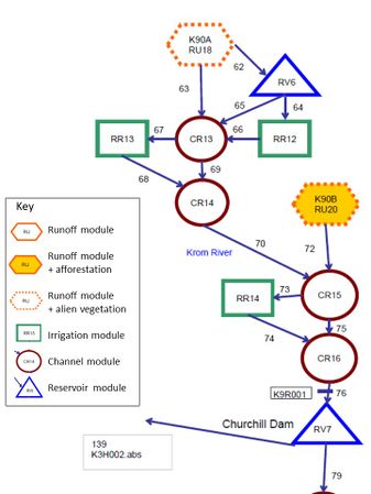
WRSM catchments are composed of ‘modules’ linked in a user-specified network.
Module types:
Subcatchments are not explicitly input, but runoff modules and sets of linked modules act as subcats. |
SPATSIM catchments are composed of subcatchments. Subcats are linked in spatially determined flow network (map input). |
ACRU4 catchments are composed of subcatchments Subcats are linked in a user-specified flow network. |
SWAT catchments are composed of subcatchments
Subcats are linked in a spatially determined flow network (delineated by SWAT from DEM input, or given as a map input) |
MIKE catchments can be composed of subcatchments Subcats are linked in spatially determined flow network (map input). |
MIKE catchments can be composed of 3D grid units. The surface is uniformly sized grid cells. Each cell has a column beneath: input layers of soil, sediment, rock.
|
| Units within
subcatchments |
A WRSM ‘runoff module’ with no linked special areas functions as a subcat. If special area modules are linked, then a set of modules functions as a subcat.
Special area modules that can be added are:
These appear as separate units, but function as sub-areas inside a specified linked runoff module.
|
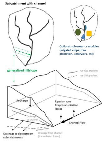
SPATSIM subcatchments all contain a river channel and may have specified special sub-areas. Subcats can optionally include either a wetland or a reservoir/lake on the channel at the subcat outlet.
A special sub-area can be defined for any, or all, of the following in a subcat:
Impervious, high ET cover, and irrigation areas do not have defined spatial locations within the subcat. |
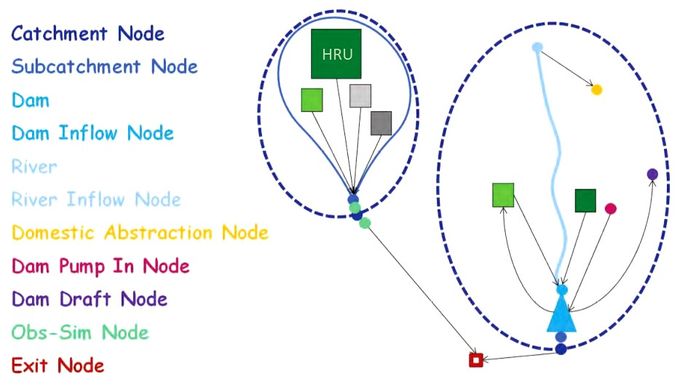
ACRU4 subcatchments are composed of one or more HRUs. Non-headwater subcats must contain a river channel. Subcats can optionally include additional channels and reservoir units. Units are linked in a user-specified network.
There are special HRUs for:
For most HRUs, all runoff is routed directly to a channel, reservoir, or subcat outlet node (in parallel). Optional exceptions: For ‘riparian HRUs’, ‘baseflow’ output from other HRUs can be routed to the riparian HRU soil. For ‘adjunct-impervious HRUs’, runoff is routed to the surface of another HRU. |
SWAT subcatchments are composed of:
Subcats can include an internal pond or wetland and a reservoir/lake on the channel at the subcat outlet.
|
MIKE-SHE subcatchments are composed of:
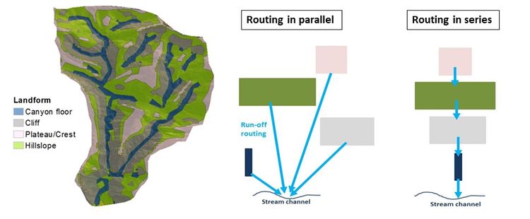
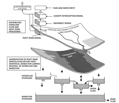
Surface runoff is lumped for grid cells within an overland flow zone & routed across zones in a downslope series to the channel (potential for infiltration on route).
Interflow reservoirs receive percolation from overlying grid cells. Interflow is laterally routed through a downslope series of reservoirs to the channel (potential for loss to recharge on route). Baselfow reservoirs are recharged by overlying interflow reservoirs and outflow to the channel in parallel. |
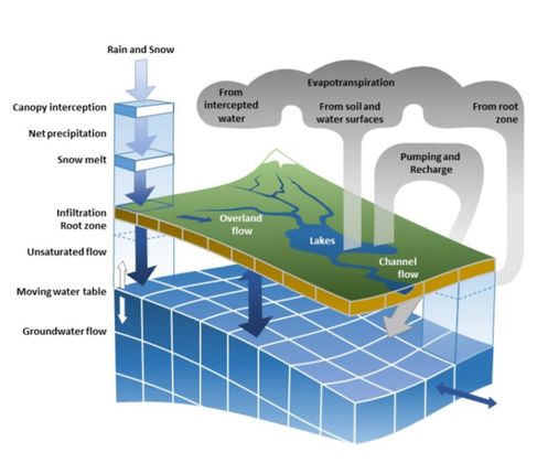
Using fully distributed MIKE-SHE, no subcat boundaries are input. Relative water surface or head elevations on the surface and in the 3D grid units drives flow exchange between units.
Different sets of zone polygons can be used for the different types of properties (e.g. vegetation types, soil types, aquifer extents); they do not need to be aligned with one another. |
| River channels | WRSM channels are modules in the network with multiple inflow and outflow links possible.
Channel modules can have an associated wetland storage/area. |
SPATSIM channels are units linked to subcats (one per subcat).
They receive the local subcat runoff & upstream subcat channel outflows. |
ACRU4 channels are units in a subcat network of units. (necessary in non-headwater subcats).
They receive runoff from linked HRUs, reservoirs, & upstream subcat outflows. |
SWAT channels are units linked to subcats (one main channel per subcat).
They receive the local subcat runoff & upstream subcat channel outflows. |
MIKE channels are composed of spatially explicit reaches between node points.
Reaches with nodes mapped inside a subcat exchange water with the subcat. |
MIKE channels are composed of spatially explicit reaches between node points.
Reaches can exchange water with grid cells that border them. |
| Units | WRSM-Pitman
(Sami GW) |
SPATSIM-Pitman
(Hughes GW) |
ACRU4 | SWAT2012 | MIKE-SHE, | MIKE-SHE, |
|---|---|---|---|---|---|---|
| Timesteps | Monthly*
|
Monthly*
|
Daily
|
Daily, subdaily
|
Daily, subdaily*
|
Daily, subdaily*
|
| Spatial units for: | ||||||
| Climate input | Modules (all) | Subcatchments | Subcatchments or HRUs*
*HRU-scale input is labor intensive |
Subcatchments | Grid cells or zones | Grid cells or zones |
| Surface & shallow subsurface processes | Runoff modules
+ special area modules |
Subcatchments
(+ internal special sub-areas) |
HRUs | HRUs | Grid cells
+ Overland flow zones + Interflow reservoir zones |
Grid cells |
| Groundwater processes | Runoff modules | Subcatchments | HRUs | Subcatchments | Baseflow reservoir zones | Grid cells |
Extra note: WRSM vs SPATSIM-Pitman structures are more similar than they appear
The WRSM-Pitman approach to model structure, with a flexible network of modules, makes it appear to be very different to SPATSIM-Pitman, which uses a clearly defined subcatchment as the basic unit of calculation for most processes. However, looking at the process algorithms for the different 'modules' in WRSM-Pitman makes it clearer that the two tools actually have relatively similar, mostly subcatchment-based, approaches. The WRSM 'runoff module', on its own with no linked special area modules, functions like a basic subcatchment of SPATSIM-Pitman with no defined sub-areas of treed cover or irrigated crops. In this case, both tools use the same subcatchment scale, monthly time-step process algorithms of the original Pitman model (Pitman 1973), both with an adjustment to include a separate aquifer store. The WRSM modules for representing commercial tree plantations and irrigated crops visually appear as separate in the model interface and network diagrams (which are generated by users, not by the software tool), but actually they function as parts of a 'runoff module'/subcatchment area. The linkage to a run-off module is established in their set-up specifications in the software. The process algorithms for these areas differ across the tools, but in both cases the treed cover modules act to increase the ET losses of the subcatchment/'runoff-module'. The resulting runoff (surface runoff, interflow, aquifer flow to channel) is generated at the subcatchment scale. For irrigated crop areas, net runoff is tied to processes calculated in the linked subcatchment in both cases as well. This means that the WRSM treed area and irrigated crop modules function more like sub-areas of subcatchments in SPATSIM than like HRUs in ACRU4, in which more processes are calculated for the HRU unit alone.
Aside from process algorithms, the main structural differences across the two tools in terms of modelled units 'inside' subcatchments are: the numbers of different special area types than can be included 'in' a subcatchment (i.e. tied to a 'runoff-module' in WRSM), the flexibility and arrangement of water sources that can be used for irrigation, and flexibility in where reservoirs, withdrawals, and transfers can be placed and how they are fed.
In terms of basic representation of a subcatchment, there is a potentially notable difference in the connection to the channel network across the tools. This is relevant to their representation of groundwater-surface water interactions. Both tools calculate aquifer-river channel exchange for the basic subcatchment unit. This is calculated within a 'runoff module' in WRSM, before the water is routed to a connected channel module. Channel modules receive the net runoff after this exchange, and do not interact further with the runoff module/subcatchment. In a sense, there is an implicit 'tributary channel' within a WRSM runoff module for which certain processes are represented, and the channel modules are a main channel network that is handled differently. In SPATSIM-Pitman, each subcatchment has a channel element that is tied to it. The channels of downstream subcatchments receive channel flow from those upstream and their channel-aquifer exchange is calculated using this accumulated channel flow. In WRSM-Pitman, this exchange is only calculated for the runoff produced in the run-off module, the incremental subcatchment, and channel flow from upstream subcatchments is not involved. The overall impact of this different on catchment-scale modelling outcomes would vary depending on how important this exchange for a given area.
Links between discretisation and process representation
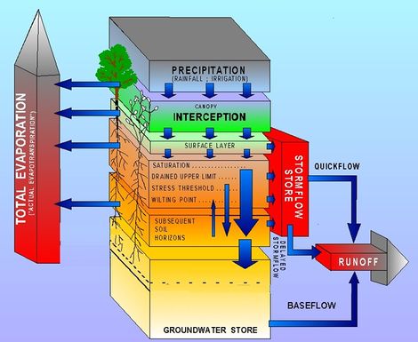
The scale of discretisation of the landscape influences which hydrological processes are individually represented and the algorithms and the timesteps that are appropriate (discussed in more detail here). In general, for larger spatial/vertical units, longer timesteps, more lumped process representation, and different property parameters are applicable compared to modelling with smaller units. This has to do with how long it’s likely to take for water to move through a modelled unit. For example, it may take a week for interflow to move through the 10 km long hillslope of subcatchment, but a day to move through the 1 km slope length of a patch of grassland within that subcatchment. Speed also vary by process and with conditions (e.g. dry and wet) which also needs some consideration in the algorithms used with a uniform calculation timesteps. Differences in algorithms and parameters with spatial scale also has to do with the fact that what may be modelled as one process at a larger spatial scale can be the result of several different processes occurring at smaller scales. For example, rain falling on a steep, rocky cliff may form surface runoff. If this surface runoff then flows across an area of permeable and unsaturated soil before reaching a stream channel, some may infiltrate and not reach the stream as surface flow. If one models a subcatchment where this is happening within a single spatial unit, the equation and parameters for estimating ‘surface runoff generation’ would account for the net outcome of the surface runoff that actually reaches the stream, i.e. the combined impact of the cliff and the permeable toe-slope on surface runoff reaching the channel. If modelling the cliff and the toe-slope as separate units, surface runoff on the cliff unit could be calculated, and then surface flow and infiltration on the toe-slope unit could be calculated as a separate set of processes, to get to the amount of surface runoff reaching the channel.
Specific units, layers, & connections
The tables below describe in more detail how the modelling tools can represent the distribution of land cover types, soil types, aquifer types, river channels, and water bodies in a catchment. They also cover vertical distribution of soil, sediment, and rock types in models, using the modelling units described above and layers within these units. The linkages or routing of water between units and layers is highlighted here, and covered in more detail in sections on process algorithms.
Land cover
| Factor | WRSM-Pitman
(Sami GW) |
SPATSIM-Pitman
(Hughes GW) |
ACRU4 | SWAT2012 | MIKE-SHE, | MIKE-SHE, |
|---|---|---|---|---|---|---|
| Spatial units for land cover type/property
distribution |
Modules & sub-areas within them | Subcatchments & sub-areas within them | HRUs | HRUs | Cover type polygons applied to grid cells | Cover type polygons applied to grid cells |
Extents of cover types are either defined in the:
Each runoff module can have different general cover specifications & linked special areas. |
Extents of cover types are defined as special sub-areas within a subcat.
Each subcat can have different general cover & sub-areas specifications. |
Each HRU has its own cover & vegetation parameters. | Each HRU has cover & vegetation parameters.
HRUs are assigned cover types using an input cover type map. Properties are input by type. |
Each grid cell is assigned a cover type using an input cover type map. Properties are input by type. | Each grid cell is assigned a cover type using an input cover type map. Properties are input by type. | |
| Limitations to types & number of types | Yes | Yes | No | No | No | No |
Types that can be represented:
|
Types that can be represented:
|
No limit on number of HRUs (hence cover types) per subcat. | No limit on number of HRUs or cover types per subcat. | No limit to number of cover types. | No limit to number of cover types. |
Soils & unsaturated zone
| Factor | WRSM-Pitman
(Sami GW) |
SPATSIM-Pitman
(Hughes GW) |
ACRU4 | SWAT2012 | MIKE-SHE, | MIKE-SHE, |
|---|---|---|---|---|---|---|
|
|
Runoff modules & irrigation modules | Subcatchments | HRUs | HRUs | Soil type polygons applied to grid cells & ‘Interflow reservoir’ extent polygons | Soil type polygons applied to grid cells |
| Each ‘runoff module’ can have its own soil moisture store & ‘percolation storage’ properties.
Afforestation & alien veg modules use the soil of the runoff module they are linked to / part of. Irrigation modules have their own soil properties. |
Each subcat can have its own soil moisture store properties. | Each HRU can have its own soil properties | Each HRU can have its own soil properties.
HRUs are assigned soil types using an input soil type map. Properties are input by soil type. Individual HRU soil properties can by modified. |
Each grid cell is assigned a soil type using an input soil type map.
Interflow reservoir ‘type’ extents are input as a map (boundaries do not need to align with soil types or subcatchments) |
Each grid cell is assigned a soil type using an input soil type map. | |
| Vertical layers in soil or UZ profile | 2 Layers | 1 Layer | 2 Layers | 11 Layers (max) | 2(3) Layers* | Unlimited Layers |
A runoff modules has 2 ‘UZ’ layers:
|
A subcat has a single soil moisture storage unit. | An HRU has 2 soil layers:
Both in root zone. |
A soil type can have up to 10 layers (user input layers).
Profile can extend below root zone. Each HRU also has a vadose zone (lag storage) ‘layer’ below the soil profile |
A soil type has vertically uniform parameters (no layers), but each model grid cell has 2 computational UZ layers:
Interflow reservoirs are storage units fed by all overlying grid cells |
A soil type can have an unlimited number of layers (user input layers).
Profile can extend below root zone. | |
| Surface runoff routing
(w.r.t. spatial units) |
Parallel* | (n/a) | Parallel | Parallel | Series or parallel | Series |
| Parallel for runoff modules & irrigation modules.
Other special area modules modify runoff module flow |
Subcatchment scale | Parallel from HRUs in subcat | Parallel from HRUs in subcat | Across a series of mapped flow zones within a subcat
OR each zone in parallel |
Across grid cells based on elevation. | |
| Interflow routing (w.r.t. spatial units) | Parallel* | (n/a) | Parallel | Parallel | Series | Series |
| Parallel for runoff modules & irrigation modules
Other special area modules modify runoff module flow |
Subcatchment scale | Parallel from HRUs in subcat | Parallel from HRUs in subcat | Through a series of interflow reservoirs in a subcat | Through grid cells based on head. | |
| Capillary rise: 2-way connection to aquifer | Yes* | Yes* | No* | Yes | Yes* | Yes |
| Only in riparian zone sub-area of runoff module; represented as ET deficit met by GW | Only in riparian zone sub-area of subcat; represented as ET deficit met by GW | Water in the baseflow store of an ACRU4 HRU cannot move into the soil profile or be used for ET in the same HRU.
BUT when upland HRU baseflow is routed to riparian HRU soil this is similar to GW access in riparian zones in subcat scale models.... |
Represented as ET deficit met by GW; access can be set by HRU | Only for grid cells in riparian zone (lowest interflow zone); represented as ET deficit met by GW |
Aquifers
| Factor | WRSM-Pitman
(Sami GW) |
SPATSIM-Pitman
(Hughes GW) |
ACRU4 | SWAT2012 | MIKE-SHE, | MIKE-SHE, |
|---|---|---|---|---|---|---|
|
Spatial units for distribution of aquifer types / properties |
Runoff modules | Subcatchments | HRUs | Subcatchments/HRUs* | ‘Baseflow reservoir’ extent polygons | Layer & lense polygons applied to grid cells |
| Each runoff module can have its own aquifer properties. | Each subcatchment module can have its own aquifer properties.
There is a spatial division into two slope sections, riparian & upslope, for process calculation, but these don’t have separate property parameters. |
Each HRU can have its own ‘baseflow storage’ properties. | Aquifer GW storage & outflow is calculated per subcat, but properties can be input per HRU to model capillary rise | ‘Baseflow reservoir’ type (aquifer type) spatial extents are input as a map (boundaries do not need to align with other inputs) | Each grid cell has a layered profile of aquifer material types based on the layers and lenses it overlies.
Property ‘layers’ cover entire the model domain, can have spatially variable thickness (grid input). ‘Lenses’ occur in certain areas (map input) also with variable thickness. | |
| Vertical layers within aquifers | 1 Layer | 1 Layer | 1 Layer | 2 Layers | 2 Layers | Unlimited Layers |
| A runoff module has one aquifer unit | A subcat has one aquifer store.
There a two linked horizontal sub sections, but no vertical divisions. |
An HRU has one ‘baseflow’ storage. | A subcat has 2 aquifer units:
|
A mapped ‘baseflow reservoir’ type can have 2 internal storage units with different parameters. | No limit on the aquifer material layers & lenses that can be input.
Calculation grid layers can be set differently to the aquifer property layers. In this case thickness-averaged parameters are assigned. | |
| GW flow routing between spatial units | Yes | Yes | (Limited) | No | No | Yes |
| GW flow between subcats | GW flow between subcats | No GW flow between subcats
Upslope HRU baseflow can be routed to riparian HRU soil within a subcat No other HRU GW exchanges included |
No GW flow between subcats | No GW flow between subcats
No GW flow between ‘baseflow reservoirs’ (aquifer types) within subcat |
GW flow between grid cells | |
| GW flow routing vertical aquifer units/layers | (n/a – single unit) | (n/a – single unit) | (n/a – single unit) | No | No | Yes |
| Shallow & deep aquifers each receive a portion of total recharge and do not interact (more like units than vertical layers) | The 2 units in a mapped baseflow reservoir type each receive a portion of total recharge and do not interact (more like units than vertical layers) | GW can flow between vertical layers based on head and conductivity | ||||
| GW flow out of model domain (catchment) | Yes | Yes | No | Yes* | No* | Yes |
| Only deep aquifer can have GW flow the model. (Deep aquifer does not feed channel, can be pumped) | Recharge can be allocated to ‘dead storage’ which has a similar impact. | GW outflow boundary condition must be set-up | ||||
| GW abstraction included | Yes | Yes | No | Yes | Yes | Yes |
| Number of abstraction points allowed | 1 per runoff module | 2 total per subcat: 1 per subcat aquifer section:
1 upslope & 1 riparian |
(n/a) | 2 total per subcat: 1 per subcat aquifer unit:
1 shallow & 1 deep |
Flexible number, location, & abstraction depth | Flexible number, location, & abstraction depth |
| GW abstraction routing options | Removed from model | Removed from model | (n/a) | Applied as irrigation, or
Removed from model |
Applied as irrigation, or
Removed from model |
Applied as irrigation, or
Removed from model |
River channel network
| Factor | WRSM-Pitman
(Sami GW) |
SPATSIM-Pitman
(Hughes GW) |
ACRU4 | SWAT2012 | MIKE-SHE, | MIKE-SHE, |
|---|---|---|---|---|---|---|
| Number of channel units by subcatchment
(or catchment) |
Flexible | 1 per subcat | Flexible | 1 per subcat* | Flexible | Flexible |
| Channels represented with channel modules in a network.
No limit to number of channel modules. Multiple connection configurations possible: max 10 input & 10 output routes per channel module. |
Subcat channel receives flow from the channels of upstream subcats & flows out to channel of downstream subcat. | Multiple channel units can be included in a network in a subcat. In non-headwater subcats a channel is needed to receive flow from upstream subcats & route to the subcat’s outflow node.
Each special riparian HRU & wetland HRU needs its own linked channel unit. No limit to the number of channel units included. |
Each subcat has one ‘main channel’ that receives flows from main channels of any upstream subcats & flows out to channel of downstream subcat. Each subcat also has one conceptual ‘tributary’ that routes HRU runoff to main channel. This allows for additional delay & loss to aquifer if relevant. | Channels are represented as a spatially explicit network of reaches between calculation nodes (cross sections) at specified intervals. Reaches with nodes mapped in subcat can exchange water with that subcat.
No limits to numbers of river branches or of reach units that can be in a subcat. |
Channels are represented as a spatially explicit network of reaches between calculation nodes (cross sections) at specified intervals. Reaches exchange water with grid cells that border them.
No limits to numbers of river branches or of reach units in a model. There cannot be two reaches in one grid cell (node spacing compatible with grid) | |
| Surface flow from land units into channel | Yes | Yes | Yes | Yes | Yes | Yes |
| Runoff, irrigation, mine modules to a linked channel module | Subcat to its channel | HRU to linked channel in subcat | All HRUs in subcat to tributary then subcat main channel | ‘Overland flow’ zones in subcat to reaches in subcat. Series routing: only from most downslope zone | Grid cells bordering a reach to that reach (if flow is over bank height) | |
| Flow from channel onto land surface (overbank flooding) | (to wetland unit only) | (to wetland unit only) | (to special riparian HRUs & wetland HRUs only) | No | Yes | Yes |
| A wetland can be included within a channel module. | A wetland can be included at downstream end of subcat. | Special HRUs for riparian areas and wetlands can be included. Each needs its own linked channel unit with an overflow threshold. | A wetland can be included in a subcat, but it is not on the ‘main channel’ or fed by overflow. | Channel flow over capacity is routed onto floodplain surface. This water can infiltrate into flooded grid cells. | Channel reach to bordering grid cells | |
| Interflow into channel | Yes | Yes | Yes | Yes | Yes | Yes* |
| Runoff, irrigation, mine modules to a linked channel module | Subcat to its channel | HRU to a linked channel in subcat | All HRUs in subcat to tributary then subcat main channel | Most downslope ‘interflow reservoir’ in subcat to reaches in subcat. | Perched, temporarily saturated layers (‘interflow’) handled in ‘saturated zone’. A channel can receive water from such a layer | |
| Flow from channel into unsaturated zone (transmission loss) | No | No | No | Yes* | No | Yes* |
| Channel transmission loss leaves the model | Channel transmission loss only to aquifer | No channel transmission loss | Main channel transmission loss goes to ‘bank storage’ – accessible for ET, not part of subcat aquifers. | Perched, temporarily saturated layers (‘interflow’) handled in ‘saturated zone’. A channel can lose water to such a layer. | ||
| Groundwater (GW) flow into channel | Yes | Yes | Yes | Yes | Yes | Yes |
| Runoff module to a linked channel module | Subcat downslope aquifer portion to subcat channel | HRU to a linked channel in subcat | Subcat shallow aquifer to channel (not from the deep aquifer) | All ‘baseflow reservoirs’ in subcat to reaches in subcat | Saturated layers of grid cells bordering a reach to that reach | |
| Flow from channel into GW
(transmission loss) |
No | Yes | No | No* | Yes | Yes |
| Channel transmission loss leaves the model | Channel to subcat aquifer (downslope portion) | No channel transmission loss | Main channel transmission loss does not enter subcat aquifer. Tributary can lose to subcat shallow aquifer | Reach in subcat to baseflow reservoir in subcat | Reach to saturated layers of grid cells bordering it | |
| Abstractions: water leave model | Yes | Yes | Yes | Yes | Yes | Yes |
| Transfers: between channels | Yes | No | No | Yes | Yes*
(complex set-up) |
Yes*
(complex set-up) |
| External water inputs | Yes | Yes | Yes | Yes | Yes | Yes |
| Abstraction, transfer, external input locations | Flexible
(avoiding circular routing) |
Subcat channel outlet (above reservoir) | Flexible | Subcat main channel outlet (above reservoir) | Flexible | Flexible |
Dams, reservoirs, lakes
| Factor | WRSM-Pitman
(Sami GW) |
SPATSIM-Pitman
(Hughes GW) |
ACRU4 | SWAT2012 | MIKE-SHE,
All approaches |
|---|---|---|---|---|---|
| Water body unit types | 1 type*:
Reservoir module |
2 types*:
Reservoir & Dam |
1 type:
Dam |
3 types*:
Reservoir, Pond, Depression |
2 approaches: explicit bathymetry+wall, storage unit |
| Wetland unit also modelled as water body (see below) | Wetland unit also modelled as water body (see below) | Wetland unit also modelled as water body (see below) | |||
| Number of units allowed per subcatchment
(or catchment) |
Flexible | 1 Reservoir per subcat
& 1 Dam per subcat |
Flexible | 1 Reservoir per subcat
& 1 Pond per subcat & multiple Depressions |
Flexible |
| Flows into water body units | Reservoir module can receive:
A reservoir receiving a set proportion of runoff from a runoff-module can be thought of as internal to the subcat that the runoff module represents. If it receives all the runoff, it’s at the subcat outlet. |
A reservoir is on the subcat channel at the outlet, so receives:
A dam is internal to a subcat & receives:
|
A dam can receive:
|
A reservoir is on the subcat channel at the outlet, so can receive:
A pond is internal to a subcat & receives:
A depression/pothole is ponded water ON a specified HRU & receives:
|
Waterbodies are handled in the channel hydraulic model (MIKE-Hydro). Waterbody bathymetry cross sections and the dimensions of a dam wall can be input in a reach of the channel. The reach could receive:
|
| Flows out of water body units | Water can leave a reservoir module as:
A reservoir can have a maximum of 5 outflow routes. |
Water can leave reservoir as:
Water can leave a dam as:
|
Water can leave a dam as:
|
Water can leave a reservoir as:
Water can leave a pond as:
Water can leave a depression water body as:
(local HRU also has: veg ET & subsurface runoff generation) |
Water can leave a reach storage created with bathymetry & a wall structure as:
Water can leave a ‘storage’ volume unit as:
|
Wetlands
'Wetlands' are challenging to generalise about because a diverse range of hydro-geomorphic settings can give rise to a frequently saturated area. The modelling tools take different approaches to representing wetlands, as described in more detail on a dedicated wetlands page, here. The table below is a brief overview of the connectivity of specific wetland modules or units in the tools. For some wetland types, other approaches besides the specifically named 'wetland' modules may actually be more relevant (e.g. riparian zone representation in various tools, 'riparian HRU' in ACRU4, 'depression/pothole' in SWAT2012)
| Component | WRSM-Pitman
(Sami GW) |
SPATSIM-Pitman
(Hughes GW) |
ACRU4 | SWAT2012 | MIKE-SHE, | MIKE-SHE, |
|---|---|---|---|---|---|---|
| Specific 'wetland' model unit |
(unit within channel module) |
Yes | Yes | Yes | No
(wetland conditions to be re-created with topography, channel, aquifer, soil, & cover set-up) |
No
(wetland conditions to be re-created with topography, channel, aquifer, soil, & cover set-up) |
| Location of wetland | On channel,
flexible location in network |
On subcat channel,
at subcat outlet |
HRU + associated channel, flexible location in network | Internal to subcat,
not on main channel |
Flexible | Flexible |
| Surface water flow into wetland | Channel flow over threshold (or all) | Channel flow over threshold (or all) | Channel flow over threshold (or all) | Proportion of subcat surface runoff | Surface runoff from upslope zone &/or channel overflow | Surface runoff from upslope cells &/or channel overflow |
| Wetland outflow to surface water | Outflow to channel module | Outflow to subcat channel outlet | Outflow routed in network
(to channel, dam, or subcat outlet node) |
Outflow to subcat main channel | Outflow to downslope zones or to channel possible | Outflow to downslope cells &/or to channel possible |
| Groundwater flow into wetland | No | No | No | Proportion of subcat subsurface runoff | Capillary rise only | Capillary rise & GW flow possible |
| Wetland seep to groundwater | No | No | Wetland HRU has own ‘baseflow store’ | Seep to subcat aquifer | Can percolate & recharge 'baseflow reservoir' | Can percolate & recharge aquifer layers |
Irrigated areas
| Component | WRSM-Pitman
(Sami GW) |
SPATSIM-Pitman
(Hughes GW) |
ACRU4 | SWAT2012 | MIKE-SHE,
All approaches |
|---|---|---|---|---|---|
| Irrigated area model units | Irrigation module | Irrigation sub-area within subcat | Irrigation HRU (special HRU) | HRU with irrigation set-up | Grid cells in 'irrigation demand areas' |
| Units (explicit crop types) per subcatchment
(or catchment) |
Unlimited | 1 sub-area per subcat | Unlimited | Unlimited | Unlimited |
| No limit to number of irrigation modules & all can have different properties. Each can also have multiple crop type sub-area entries: area-weighted averaging of properties is done in the model. | Area can be subdivided into river-fed and dam-fed, but only one irrigation demand set (hence crop type) input. | Irrigation can be set-up for any HRU in the ‘management parameters’
Land cover input & delineation of HRUs occurs separately. |
An ‘irrigation demand area’ map input (extents of irrigated areas by scheduling type) determines if a grid cell is irrigated.
The separate land cover map input determines the cell’s veg type/crop. | ||
| Number of irrigation water sources allowed per unit | 1 source per module | 2 sources per subcat:
1 source per portion of total irrigated area |
1 source per HRU | Multiple sources for an HRU as scheduled | Multiple sources per irrigated area: switch sources with water availability |
| The subcat irrigated area can have a % that is river-fed & % dam-fed, but no one place can be fed by both sources. | HRU irrigation schedule can be set-up with different methods & sources at different specified times. For each time entry only one water source can be selected: cannot set to switch between sources based on their water availability. | Multiple potential sources can be specified with an order of preference. If water supply is lacking (or licensed use amount reached) at a higher listed source, irrigation will be drawn from the next source possible in the list. | |||
| Irrigation water source type options: | |||||
| River | Yes | Yes | Yes | Yes | Yes |
| Dams/reservoirs | Yes | Yes* | Yes | Yes* | Yes* |
| Only from ‘dam’ (fed by local runoff); NOT ‘reservoir’ (on channel; upstream inputs) | Only 'reservoir', NOT 'ponds' or 'depressions/potholes' | Only from part of a channel reach (explicit bathymetry & wall), NOT simple 'storage' | |||
| Aquifers | No | No | No | Yes | Yes |
| External source | Yes | Yes | Yes | Yes | Yes |
| Restrictions on source locations | Flexible (must be different to module receiving return flow) | Only sources within same subcat | Sources in subcat, or dams in upstream subcats | Flexible (not restricted to same subcat) | Flexible (not restricted to same subcat) |
| ‘Return flow’ routing options | To any channel or reservoir module (that is not the source module) | To subcat channel | To a subcat channel, reservoir, or the outflow node | To subcat channel | Downslope cells &/or channel |
| Part of subcat-scale runoff handling | Handled same as other HRUs. | Handled same as other HRUs
Can add tile drains: also route to channel, changes rate |
Handled same as other grid cells
Can add tile drains: drain to point in river, changes rate | ||
